2 Channel USB Relay Module


Request For QuoteWanna Customize? Drop Us A Line!
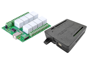
Numato Lab 2 Channel USB Relay Module is great for controlling your devices through USB without any USB protocol knowledge. This module plugs into your design seamlessly. Individual relay can be controlled by simple commands. Numato’s URMC2 2 Channel USB Relay Module provides exceptional value for money.
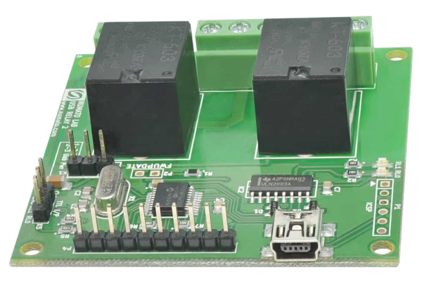
It has two onboard 12V relays that can switch up to 10A load. It comes with built-in firmware that supports simple commands to control relays and read relay status. The board, when attached to a PC/Laptop shows up as a serial port and all you need to control the board is a serial terminal application like HyperTerminal or Putty. This board can easily be controlled by writing simple serial port applications in VC++, VB, VBA (Word, Excell, etc), Perl, Python, etc.
Features
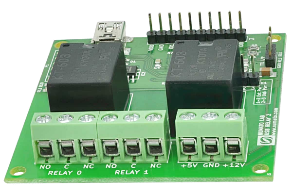
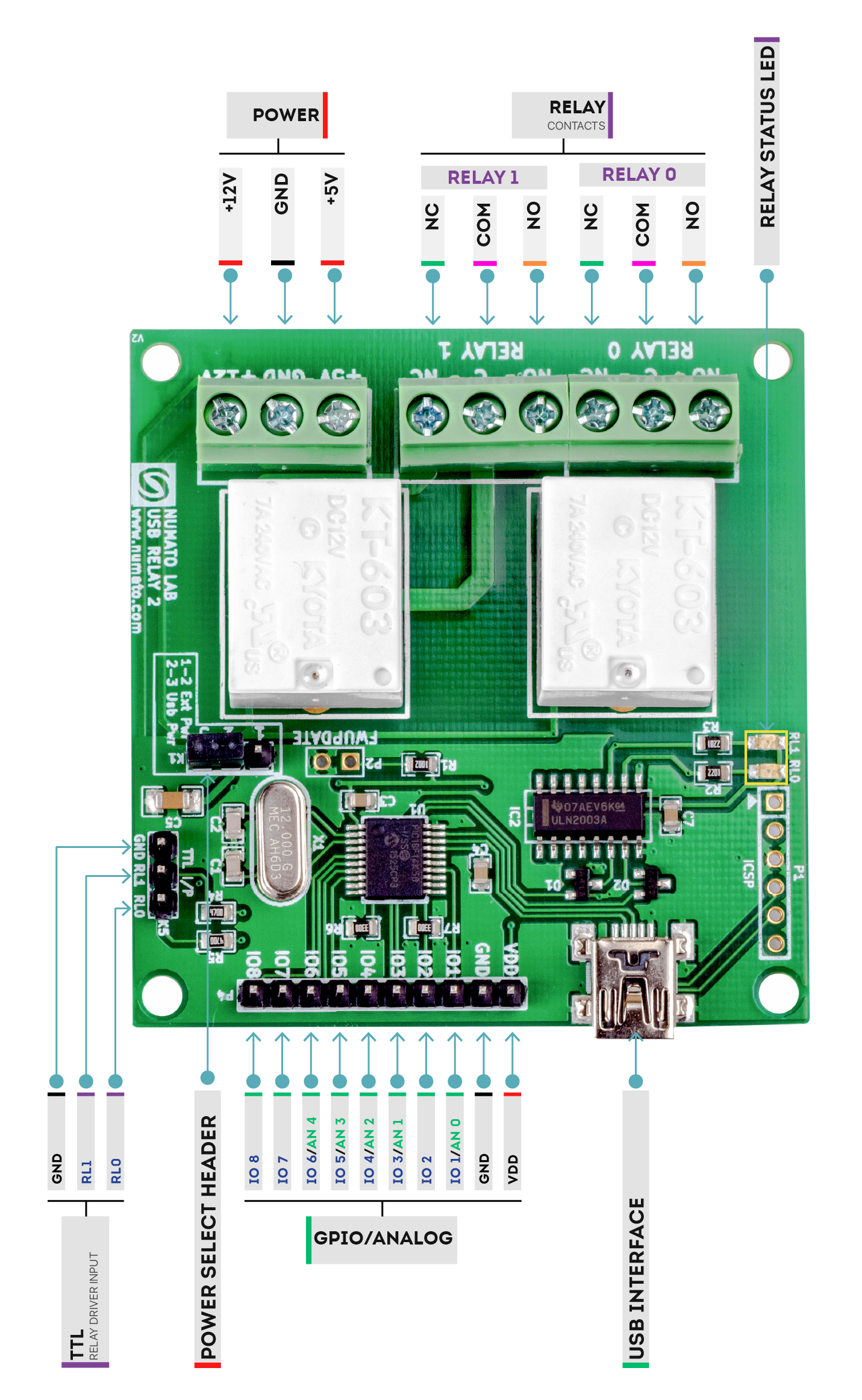
- 2 onboard 12V SPDT Relays.
- 7A Maximum Switching Current.
- 8 TTL (5V)Compatible GPIOs.
- 6 Analog Input Channel(Multiplexed with GPIOs).
- 10 Bit Analog Input Resolution.
- USB interface with CDC support. As easy as using a serial port, no USB knowledge required.
- Relay contacts available on easy to access screw terminals.
- Digital circuitry can be powered from USB or external power supply.
- Can be controlled by using standard serial console applications or custom applications.
- No vendor specific libraries or APIs required.
Applications
- Home Automation
- Industrial Automation
- Lighting Control
- Garden Equipment Control
- Test Fixtures
- DIY and Hobby
Supporting Operating Systems
- Windows XP and later
- Windows 7 Embedded and later
- Linux
- Mac OS X
- Android
- or any other operating system that supports USB CDC devices.
Languages that can be used for programming
- C/C++
- Visual Basic (VB6, VB2008, VB2010 express and other editions)
- Visual Basic for Applications (Microsoft Office VBA)
- Perl
- Python
- JAVA
- Android
- Javascript(Node.js)
- And many more…
Specifications
| Attribute | Value |
|---|---|
| Weight | 0.2 lbs |
| Dimensions | 5 × 3 × 1 in |
| Product Dimensions | 2.48 x 2.40 x 0.59 in |
| Number Of Relays | 2 |
| Relay Type | |
| Max Relay Current Rating | 10A |
| Number Of GPIOs (Max) | |
| Analog Inputs(Max) | |
| Analog Input Resolution | |
| Communication | USB |
| USB Connector | Mini B |
Sample Code
Sample Code
| Language/Technology | IDE/Compiler | Type | OS | Download link |
|---|---|---|---|---|
| C | VCExpress2008 | Command Line | Windows | Download |
| C | VCExpress2010 | Command Line | Windows | Download |
| Visual Basic | VBExpress2008 | GUI | Windows | Download |
| Visual Basic | VBExpress2010 | GUI | Windows | Download |
| Visual Basic | Visual Basic 6 | GUI | Windows | Download |
| C | Visual C++ 6 | Command Line | Windows | Download |
| Python | Python | Command Line | Windows | Download |
| Java | NetBeans | Command Line | Any | Download |
| C# | Visual Studio 2012 | GUI | Windows | Download |
| AutoHotkey | AutoHotkey | GUI | Windows | Download |
| VBA | MS Excel 2010 | GUI | Windows | Download |
| VBA | MS Word 2010 | GUI | Windows | Download |
| Visual Basic | JustBASIC | NA | Windows | Download |
| Javascript | Node.js | Command Line | Windows | Download |
| AutoIt | AutoIt | NA | Windows | Download |
| Labview | Labview | Simple GUI | Any | Download |
| Perl | Perl | Command Line | Linux | Download |
| Perl | Perl | Command Line | Windows | Download |
Related products
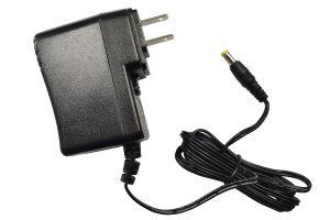
AC/DC Wall Mount Switching Mode Power Supply
Starts at $17.99